Lesson 10 of 16 · 25 min
Control a DC Motor with Arduino and a Transistor
An Arduino pin cannot supply the 200 mA or more a DC motor draws, so a transistor (TIP120) switches the motor’s current while the pin only provides about 1 mA into the base, and a flyback diode absorbs the voltage spike when the motor stops.
This lesson also runs on an interactive 3D board: wire it, press Run and watch the circuit respond.
Open the 3D lessonA small DC motor draws 200–300 mA running and several times that when it starts. An Arduino pin is rated for 20 mA, so connecting the motor directly either does nothing or destroys the output stage. A transistor is the switch in between: the pin controls it, the transistor carries the motor current.
The second thing the motor needs is a diode. A spinning motor is also a generator, and when you cut the power its inductance pushes a voltage spike back up the wire — often tens of volts. A 1N4001 across the motor, stripe towards +, shorts that spike safely.
What you need
| Part | Qty | Notes |
|---|---|---|
| Arduino Uno R3 | 1 | Pin 6 is a PWM pin |
| 3–6 V DC motor | 1 | Toy motor, ~200 mA free running |
| TIP120 Darlington transistor | 1 | Handles 5 A; a 2N2222 works for tiny motors |
| 1 kΩ resistor | 1 | Brown-black-red, protects the base |
| 1N4001 diode | 1 | Flyback protection, stripe to + |
| External 5 V supply | 1 | Or 4×AA cells: never power the motor from the board |
How to wire it
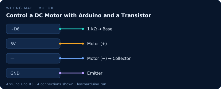
Motor + → external +. Motor − → TIP120 collector (middle leg). TIP120 emitter → common ground. Pin 6 → 1 kΩ → TIP120 base (left leg). 1N4001 across the motor, stripe towards +. The external supply ground and the Arduino ground must be joined.
| Pin | Connects to | What it does |
|---|---|---|
| ~D6 | 1 kΩ → Base | PWM signal from the sketch. |
| 5V | Motor (+) | Motor supply. |
| — | Motor (−) → Collector | The transistor completes the motor circuit. |
| GND | Emitter | Shared ground. |
Driving an Arduino DC motor safely
A pin gives 20 mA; a small motor wants 200–300 mA running and several times that at stall. The transistor is the switch in between: 1 kΩ from the pin to the base, emitter to ground, collector to the motor's negative lead, motor positive to its own supply. The Arduino never sees the motor current.
TIP120 is the part in most kits and it works, but it is a Darlington pair with a saturation voltage near 2 V, so a 5 V motor only sees about 3 V and the transistor gets warm. A logic-level MOSFET such as the IRLZ44N drops a fraction of a volt instead and stays cool — the better choice if you are buying parts rather than using what is in the box.
Choosing a transistor, a driver or a shield
One transistor switches one direction. If the project needs reverse, two motors, or braking, an H-bridge module is the honest answer: the L298N is cheap and drops 1.4–2 V, the TB6612FNG is smaller and much more efficient. Both take a PWM pin and two direction pins per motor.
Whatever the switch, the diode stays. A motor is also a generator, and cutting its current makes the inductance throw a spike back up the wire that will destroy a transistor the first time it happens. 1N4001 across the motor with the stripe to positive, plus a 100 nF capacitor across the terminals so the brushes stop broadcasting noise into the rest of the circuit.
The sketch
const int MOTOR = 6;  // PWM pin drives the transistor base

void setup() {
  pinMode(MOTOR, OUTPUT);
}

void loop() {
  // ramp up: 0 to full speed
  for (int speed = 0; speed <= 255; speed += 5) {
    analogWrite(MOTOR, speed);
    delay(40);
  }

  delay(1500);            // hold top speed

  analogWrite(MOTOR, 0);  // coast to a stop
  delay(1500);
}
What the code does
- analogWrite(MOTOR, s) sets the duty cycle: 0 is off, 255 is full speed, 128 is about half.
- The for loop raises the speed in steps of 5 every 40 ms, which sounds and looks like a smooth ramp.
- Analog output is really fast switching — the motor averages the pulses into a speed.
- Writing 0 at the end lets the motor coast rather than brake, which is gentler on the gearbox.
Specifications
| Item | Value |
|---|---|
| Motor | 3–6 V DC, ~200 mA |
| Transistor | TIP120 Darlington, 5 A |
| Base resistor | 1 kΩ (brown-black-red) |
| PWM on pin 6 | ≈ 980 Hz |
| Tip | Add a flyback diode across the motor |
Common mistakes
- Powering the motor from the Arduino’s 5 V pin. The regulator overheats and the board resets every time the motor starts.
- Leaving out the flyback diode. The first time the motor stops, the spike can kill the transistor — sometimes the Arduino too.
- Forgetting to join the grounds. Without a shared ground the base voltage has no reference and the transistor stays half-on.
Sources
The figures in this lesson come from these documents. Every value in the tables above can be checked against them.
- Transistor motor control — Arduino documentation
- analogWrite() — Arduino language reference
- Arduino Uno Rev3 — official board specifications
Frequently asked questions
Can an Arduino power a DC motor directly?
No. A pin supplies at most 40 mA and the board’s regulator about 400 mA in total, while a small motor needs 200–300 mA just to run. Use a transistor or a motor driver and a separate supply.
Why do I need a diode across the motor?
The motor’s coils store energy. When the transistor switches off, that energy becomes a voltage spike that can exceed 50 V and destroy the transistor. The diode gives it a loop to discharge through.
What is the difference between a transistor and an L298N driver?
A single transistor switches one direction only. A driver such as the L298N or TB6612 has two H-bridges, so it can run two motors forwards and backwards with speed control.
How do I make the motor run slower without stalling?
Below about 20% duty cycle most toy motors do not have enough torque to start. Either start with a kick at 60% for 100 ms, or ramp up gradually from 0 as the sketch here does.
Want to see this circuit before you own the parts? The Arduino simulator draws this exact pin table on a 3D Uno R3: click any jumper to see what it carries, press Run and read the serial monitor.
Open the Arduino simulatorPublished 12 November 2026 · last updated 19 November 2026 · written and tested by Nick Hu.