Lesson 7 of 16 · 25 min
Arduino Ultrasonic Sensor: HC-SR04 Distance Guide
The HC-SR04 measures distance by timing an echo: distance in centimetres = echo time in microseconds ÷ 58, because sound takes about 29 µs to travel one centimetre each way.
This lesson also runs on an interactive 3D board: wire it, press Run and watch the circuit respond.
Open the 3D lessonThe HC-SR04 fires a burst of 40 kHz ultrasound from one cylinder and listens with the other. A 10 µs pulse on the Trig pin starts a ping, and the Echo pin goes HIGH for exactly as long as the sound takes to travel out and back.
Sound covers about 343 m per second, which is 0.0343 cm per microsecond. The echo covers the distance twice, so one centimetre of range costs about 58 µs of echo time. Divide the measured pulse by 58 and you have centimetres, no calibration needed.
What you need
| Part | Qty | Notes |
|---|---|---|
| Arduino Uno R3 | 1 | Trig on pin 9, Echo on pin 10 |
| HC-SR04 sensor | 1 | 4 pins: VCC, Trig, Echo, GND |
| Breadboard + 4 jumpers | 1 | The sensor needs 5 V and 15 mA |
| A flat target | 1 | A book or a hand works; soft cloth absorbs sound |
How to wire it
VCC → 5 V, GND → GND, Trig → pin 9, Echo → pin 10. Keep the sensor facing the target straight on: the beam is a 15° cone, so a tilted surface bounces the echo away.
| Pin | Connects to | What it does |
|---|---|---|
| 5V | VCC | Powers the sensor. |
| GND | Gnd | Common ground. |
| D9 | Trig | A 10 µs HIGH pulse starts a ping. |
| D10 | Echo | Stays HIGH for as long as the sound travels. |
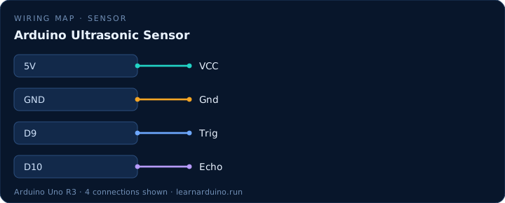
How to wire an Arduino ultrasonic sensor (HC-SR04)
Four wires and no resistors on a 5 V board. VCC to 5 V, GND to ground, Trig to a digital output, Echo to a digital input — D9 and D10 here. The module draws about 15 mA while pinging, well inside what a pin-fed 5 V rail can give, and its Echo output is a clean 5 V pulse the Uno reads directly.
Mounting matters more than wiring. The two cylinders are the transmitter and the receiver, and the beam between them is a cone of roughly 15°, so the sensor has to face the target squarely. A soft surface — a curtain, a sleeve, a cat — absorbs the 40 kHz burst and returns nothing, which reads as out of range rather than as a distance.
Range, blind zone and unreliable echoes
The HC-SR04 is specified from 2 cm to 400 cm at about ±3 mm, and the 2 cm floor is real: closer than that, the echo returns before the module has finished transmitting. Readings of 0, or anything above 400, mean no usable echo came back — the sketch should say so rather than print a number.
Sound travels at about 343 m/s at 20 °C and the figure moves roughly 0.6 m/s per degree, so the 58 µs-per-centimetre constant drifts a few percent between a cold garage and a warm room. Two sensors aimed at the same space interfere with each other; take three readings and use the median, and leave 60 ms between pings so the previous burst dies away.
The sketch
const int TRIG = 9;
const int ECHO = 10;

void setup() {
  Serial.begin(9600);
  pinMode(TRIG, OUTPUT);
  pinMode(ECHO, INPUT);
}

void loop() {
  // 10 us pulse starts one ping
  digitalWrite(TRIG, HIGH);
  delayMicroseconds(10);
  digitalWrite(TRIG, LOW);

  // Echo stays HIGH for the round trip
  long us = pulseIn(ECHO, HIGH, 30000);  // 30 ms timeout
  long cm = us / 58;                     // 58 us per cm, both ways

  if (cm == 0 || cm > 400) Serial.println("out of range");
  else Serial.println(cm);

  delay(60);  // let the echo die away before the next ping
}
What the code does
- A 10 µs HIGH pulse on Trig is the whole trigger sequence; any longer and the sensor ignores it.
- pulseIn(ECHO, HIGH) blocks until the echo returns, so a missing target stalls the sketch for up to a second.
- Dividing by 58 converts microseconds to centimetres; divide by 148 for inches.
- Readings of 0 or over 400 cm mean no echo came back — treat them as “out of range”, not as a real distance.
Specifications
| Item | Value |
|---|---|
| Range | 2–400 cm |
| Resolution | ≈ 3 mm |
| Frequency | 40 kHz |
| Beam angle | ≈ 15° |
| Supply | 5 V, 15 mA |
Common mistakes
- Powering the HC-SR04 from 3.3 V. It needs 5 V and will return garbage or nothing below about 4.5 V.
- Measuring a soft or angled target. Curtains, clothing and slanted boxes swallow or deflect the echo, so the reading jumps to 0.
- Calling pulseIn() without a timeout in a loop that also drives a motor. A missing echo then freezes the whole sketch for a second at a time.
Sources
The figures in this lesson come from these documents. Every value in the tables above can be checked against them.
- HC-SR04 — pinout, timing and range
- pulseIn() — Arduino language reference
- Arduino Uno Rev3 — official board specifications
Frequently asked questions
How accurate is the HC-SR04?
About ±3 mm in good conditions, with a usable range of 2–400 cm. Accuracy falls off above 2 m and with soft or angled targets, so treat anything past 3 m as a rough estimate.
Why does my ultrasonic sensor read 0?
No echo came back within the timeout: the target is too far, too soft, too angled, or the sensor is wired to the wrong pins. Print the raw pulseIn() value — 0 means no echo at all.
Can I use one ultrasonic sensor on two Arduinos?
Not directly. Two HC-SR04s facing each other interfere; alternate them (ping A, wait 60 ms, ping B) or use sensors that trigger on different codes.
Do I need a resistor on the Echo pin?
Not with a 5 V Uno: Echo outputs 5 V, which the Uno tolerates. On a 3.3 V board such as an ESP32 you must divide Echo down with two resistors.
Want to see this circuit before you own the parts? The Arduino simulator draws this exact pin table on a 3D Uno R3: click any jumper to see what it carries, press Run and read the serial monitor.
Open the Arduino simulatorPublished 12 November 2026 · last updated 19 November 2026 · written and tested by Nick Hu.