Lesson 16 of 16 · 30 min
Arduino Uno Projects: Build a Smart Traffic Light
This project combines an HC-SR04 distance sensor with a red-yellow-green traffic light module: the Arduino measures the gap and lights exactly one lamp — red under 15 cm, yellow to 30 cm, green beyond.
This lesson also runs on an interactive 3D board: wire it, press Run and watch the circuit respond.
Open the 3D lessonThis is the lesson where the previous fifteen pay off: a sensor input, three outputs, and a decision in between. The distance code is the same as lesson 7; the difference is that the measurement now drives something you can see from across the room.
It is also the smallest complete project you can show someone. Put it on a cardboard road with a toy car and it reads as a traffic system, which makes it a good first thing to build outside the browser.
What you need
| Part | Qty | Notes |
|---|---|---|
| Arduino Uno R3 | 1 | One board runs everything |
| HC-SR04 sensor | 1 | Trig on pin 9, Echo on pin 10 |
| Traffic light module | 1 | Or three LEDs with 220 Ω resistors |
| Breadboard + 8 jumpers | 1 | GND is shared between sensor and lights |
| Cardboard + toy car | 1 | Optional, but it sells the demo |
How to wire it
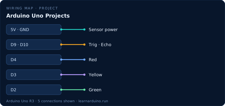
Sensor: VCC → 5 V, GND → GND, Trig → D9, Echo → D10. Lights: red → D4, yellow → D3, green → D2, with the module’s GND joined to the same rail. Three separate LEDs need a 220 Ω resistor each.
| Pin | Connects to | What it does |
|---|---|---|
| 5V · GND | Sensor power | GND is bridged to the light module. |
| D9 · D10 | Trig · Echo | Same as lesson 7. |
| D4 | Red | On when the obstacle is close. |
| D3 | Yellow | On in between. |
| D2 | Green | On when it is far away. |
Choosing Arduino Uno projects to build next
The useful progression is one new capability per project: an input you have not used, an output you have not driven, or a structure you have not written. A sensor plus a visible output is the shape that teaches most — distance and a traffic light, light and a night light, force and a gauge.
This build is deliberately small so it can grow, and every extension is a lesson you have already done: a buzzer for the blind (lesson 8), an OLED showing the measured distance (lesson 14), a servo lifting a barrier (lesson 12), a stepper turning a turntable (lesson 13). Power bites first — budget 20 mA per pin and about 400 mA from the 5 V pin, and give anything with a motor its own supply.
Making the traffic light behave like a real one
Real controllers are state machines, not if-statements. Each state has a minimum duration, a yellow that lasts about three seconds, and a rule for what may follow it. Written with millis() instead of delay(), the loop keeps measuring distance while the lights run their sequence.
Add a night mode that flashes amber when nobody is waiting, and a car detector with hysteresis so a parked toy does not hold the light red forever. That is the same pattern a pedestrian crossing uses, and it is the point where the project stops being a demo and starts being a system.
The sketch
const int TRIG = 9, ECHO = 10;
const int RED = 4, YELLOW = 3, GREEN = 2;

void setup() {
  pinMode(TRIG, OUTPUT);
  pinMode(ECHO, INPUT);
  pinMode(RED, OUTPUT);
  pinMode(YELLOW, OUTPUT);
  pinMode(GREEN, OUTPUT);
  Serial.begin(9600);
}

void loop() {
  digitalWrite(TRIG, HIGH);
  delayMicroseconds(10);
  digitalWrite(TRIG, LOW);

  long cm = pulseIn(ECHO, HIGH, 30000) / 58;
  Serial.println(cm);

  // exactly one lamp is on at a time
  digitalWrite(RED,    cm > 0 && cm <= 15);
  digitalWrite(YELLOW, cm > 15 && cm <= 30);
  digitalWrite(GREEN,  cm > 30 || cm == 0);

  delay(60);
}
What the code does
- The trigger and echo sequence is identical to the ultrasonic lesson — the sensor does not care what you do with the number.
- digitalWrite(GRN, cm > 30) writes a comparison straight to a pin: true becomes HIGH, false becomes LOW.
- The three conditions are mutually exclusive, so exactly one lamp is lit at any moment.
- delay(60) gives the echo time to fade between pings and keeps the lights from flickering.
Specifications
| Item | Value |
|---|---|
| Parts | Uno, HC-SR04, traffic light module |
| Wires | 8 jumpers |
| Thresholds | Adjustable |
| Update rate | ≈ 15 times a second |
| Next step | Add a buzzer from lesson 8 |
Common mistakes
- Powering the light module from a pin. Three lamps at 20 mA each is at the limit; use the 5 V pin and switch them with transistors if they are bright.
- Mounting the sensor at an angle. The 15° beam then misses the car and the lights jump between green and red.
- Forgetting the shared ground between sensor and lights. The readings then drift and the lamps glow dimly when they should be off.
Sources
The figures in this lesson come from these documents. Every value in the tables above can be checked against them.
- HC-SR04 — pinout, timing and range
- pulseIn() — Arduino language reference
- digitalWrite() — Arduino language reference
Frequently asked questions
What is a good first Arduino Uno project?
A sensor plus a visible output: a distance sensor with a traffic light, a light sensor with a night light, or a button with a buzzer. Each one needs under ten components and teaches input, logic and output in one build.
How many components can an Arduino Uno project use?
As many as you can power and address. Practical limits are 20 mA per pin, 200 mA total from the pins and about 400 mA from the 5 V pin — beyond that, add an external supply and drivers.
How do I make the traffic light more realistic?
Add a state machine with millis(): each light gets a minimum duration, and a car waiting at red starts a countdown. That is the same pattern real controllers use, and it removes every delay() from the sketch.
Can I add sound or a display to this project?
Yes — a piezo buzzer on pin 8 beeps when the light turns red (lesson 8), and an SSD1306 OLED on A4/A5 can show the measured distance (lesson 14). Both reuse code you already have.
Want to see this circuit before you own the parts? The Arduino simulator draws this exact pin table on a 3D Uno R3: click any jumper to see what it carries, press Run and read the serial monitor.
Open the Arduino simulatorPublished 12 November 2026 · last updated 19 November 2026 · written and tested by Nick Hu.