Lesson 13 of 16 · 35 min
Arduino Stepper Motor: 28BYJ-48 and ULN2003
A 28BYJ-48 stepper motor takes 2048 half-steps for one full revolution (64 steps × a 32:1 gearbox), and an Arduino drives it through a ULN2003 board using four pins, one per coil.
This lesson also runs on an interactive 3D board: wire it, press Run and watch the circuit respond.
Open the 3D lessonA stepper motor does not spin because you applied power — it turns because you energise its coils in sequence, one step at a time. Count the steps and you know the angle exactly. That is why steppers appear in 3D printers, camera sliders and pointer dials.
The 28BYJ-48 in every starter kit is geared 64:1, so one output turn costs 2048 half-steps. It is slow and quiet and cannot be back-driven easily — exactly what you want for a dial or a small turntable.
What you need
| Part | Qty | Notes |
|---|---|---|
| Arduino Uno R3 | 1 | Pins 8–11 drive the coils |
| 28BYJ-48 stepper | 1 | 5 V, unipolar, 5-wire ribbon |
| ULN2003 driver board | 1 | Comes with the motor; has 4 indicator LEDs |
| External 5 V supply | 1 | The coils draw ~240 mA, more than a pin can give |
How to wire it
Motor ribbon → ULN2003 socket (only fits one way). ULN2003 IN1–IN4 → pins 8, 9, 10, 11. Board + → 5 V, − → GND. With AccelStepper the pin order is 8, 10, 9, 11 — IN1, IN3, IN2, IN4 — which is the order the coils actually fire in.
| Pin | Connects to | What it does |
|---|---|---|
| D8–D11 | IN1–IN4 | One pin per coil, through the ULN2003. |
| 5V · GND | Driver + and − | The coils need more current than a pin can give. |
| D2 | Button | HIGH while pressed (10 kΩ pull-down). |
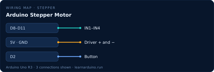
Driving an Arduino stepper motor with a ULN2003
The 28BYJ-48 is a unipolar stepper: five wires, four coils with a common centre tap, and a ULN2003 board that switches those coils from four logic inputs. The ribbon connector only fits one way, which is a mercy, because the coil order is where most builds fail.
IN1–IN4 go to four digital pins, and the order matters more than the numbers suggest. With AccelStepper the pins are declared as 8, 10, 9, 11 — IN1, IN3, IN2, IN4 — because that is the sequence the coils actually fire in. Wire them 8, 9, 10, 11 and the motor buzzes in place instead of turning, which reads as a dead motor.
Positioning without losing steps
A stepper has no feedback. It moves because the coils were energised in order, and it assumes every step landed — so a step lost to excess speed or low current becomes a permanent position error. Acceleration is not a nicety: setMaxSpeed() without setAcceleration() makes the motor stall and skip above a few hundred steps per second.
The coils draw about 240 mA with two energised, more than the board should give through its 5 V pin, and the driver gets warm. A separate 5 V supply with a shared ground fixes the first problem; a small heatsink and not holding position for hours fixes the second. Homing against a limit switch is how a real machine turns counting into knowing.
The sketch
#include <AccelStepper.h>

const int STEPS_PER_TURN = 2048;   // 28BYJ-48, half-step mode
const int BUTTON = 2;

// coil order for this motor: IN1, IN3, IN2, IN4
AccelStepper wheel(AccelStepper::FULL4WIRE, 8, 10, 9, 11);

void setup() {
  pinMode(BUTTON, INPUT);
  wheel.setMaxSpeed(1024);    // steps per second (~30 RPM)
  wheel.setAcceleration(512); // ramp, so it never skips
  randomSeed(analogRead(A0));
  Serial.begin(9600);
}

void loop() {
  if (digitalRead(BUTTON) == HIGH) {
    int segment = random(8);                    // 8 prizes on the wheel
    long steps = (long)STEPS_PER_TURN + segment * (STEPS_PER_TURN / 8);
    wheel.move(steps);                          // one full turn plus the offset

    wheel.runToPosition();                      // accelerate, spin, settle
    Serial.print("Landed on segment ");
    Serial.println(segment + 1);
  }
}
What the code does
- AccelStepper(AccelStepper::FULL4WIRE, 8, 10, 9, 11) declares four-wire drive with the coil order this motor expects.
- setMaxSpeed() is in steps per second: 2048 steps per rev means 1024 steps/s is 30 RPM.
- move() queues a relative move and runToPosition() blocks until it arrives, accelerating and decelerating on the way.
- randomSeed(analogRead(A0)) gives a different sequence every time the board powers up; without it random() repeats.
Specifications
| Item | Value |
|---|---|
| Motor | 28BYJ-48, 5 V |
| Steps per turn | 2048 (64 : 1 gearbox) |
| Driver | ULN2003 Darlington array |
| Speed | ≈ 15 RPM from a standstill, more with a ramp |
| Segments | 8 × 256 steps |
Common mistakes
- Wiring IN1–IN4 in numeric order. The motor then vibrates in place instead of turning, because the coils fire in the wrong sequence.
- Powering the ULN2003 from the Arduino 5 V pin. Four coils at 60 mA each brown out the board; use a separate 5 V supply with a shared ground.
- Calling runToPosition() inside a tight loop with other work. It blocks; use run() with a target instead if the sketch must keep reading sensors.
Sources
The figures in this lesson come from these documents. Every value in the tables above can be checked against them.
- 28BYJ-48 — coil order and gear ratio
- AccelStepper library — Arduino reference
- digitalWrite() — Arduino language reference
Frequently asked questions
How many steps does a 28BYJ-48 take for one revolution?
2048 half-steps in the usual half-step mode: 64 steps per internal revolution times the 32:1 gearbox, with a small correction for the true gear ratio. In full-step mode it is 1024.
Why does my stepper just vibrate?
The coil order is wrong or one wire is loose. Check that IN1–IN4 map to 8, 10, 9, 11 with AccelStepper, and that the ribbon is fully seated in the driver board.
Can I power a stepper from the Arduino?
Not reliably. The 28BYJ-48 draws about 240 mA with two coils energised, which is more than the board should supply through its 5 V pin. Use 4×AA or a 5 V 1 A adapter.
How do I make a stepper spin faster?
Raise setMaxSpeed() and setAcceleration() together. Without acceleration the motor skips steps above a few hundred steps per second and loses its position.
Want to see this circuit before you own the parts? The Arduino simulator draws this exact pin table on a 3D Uno R3: click any jumper to see what it carries, press Run and read the serial monitor.
Open the Arduino simulatorPublished 12 November 2026 · last updated 19 November 2026 · written and tested by Nick Hu.