Lesson 5 of 16 · 20 min
Arduino RGB LED: Mix Any Colour with Three PWM Pins
An RGB LED is three LEDs in one package — red, green and blue — each with its own series resistor on a PWM pin, so analogWrite() values from 0 to 255 per channel mix about 16.7 million colours.
This lesson also runs on an interactive 3D board: wire it, press Run and watch the circuit respond.
Open the 3D lessonAn RGB LED has four legs: one common leg and one for each colour. In a common-cathode part the common leg goes to ground and each colour lights when its pin goes HIGH. In a common-anode part the common leg goes to 5 V and the logic is inverted — check yours before wiring.
Each colour needs its own resistor because red drops about 2 V while green and blue drop about 3 V. 220 Ω per channel gives roughly 14 mA on red and 9 mA on green and blue: bright, safe, and close enough that the mix looks balanced.
What you need
| Part | Qty | Notes |
|---|---|---|
| Arduino Uno R3 | 1 | PWM pins 9, 10 and 11 |
| 5 mm RGB LED | 1 | Common cathode; the longest leg is the common one |
| 220 Ω resistor | 3 | One per colour — never one shared resistor |
| Breadboard + 4 jumpers | 1 | Four legs, four wires |
How to wire it
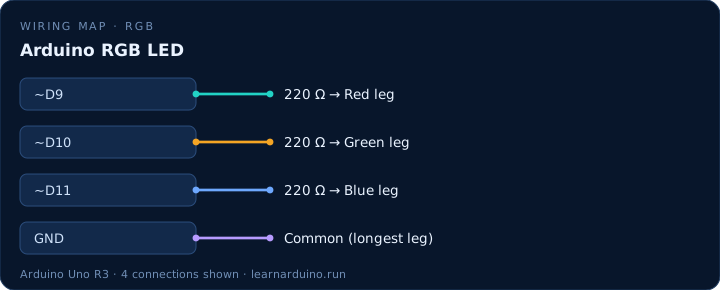
Longest leg (common cathode) → GND. Red leg → 220 Ω → pin 9, green leg → 220 Ω → pin 10, blue leg → 220 Ω → pin 11. For a common-anode LED, common → 5 V and invert every value: 255 − value.
| Pin | Connects to | What it does |
|---|---|---|
| ~D9 | 220 Ω → Red leg | Brightness of the red LED. |
| ~D10 | 220 Ω → Green leg | Brightness of the green LED. |
| ~D11 | 220 Ω → Blue leg | Brightness of the blue LED. |
| GND | Common (longest leg) | All three LEDs return here. |
Choosing resistors for an Arduino RGB LED
One resistor for three colours is the mistake that makes mixed colours look muddy. Red drops about 2 V while green and blue drop about 3.2 V, so the same resistor gives very different currents: (5 − 2) ÷ 220 ≈ 14 mA on red against (5 − 3.2) ÷ 220 ≈ 8 mA on green and blue. That imbalance is why “white” comes out pink.
One 220 Ω per leg gets you close. For a balanced white, size each channel from its own forward voltage — 220 Ω on red with 150 Ω on green and blue is a typical set. Keep the three pins under about 60 mA in total and you stay well inside the 200 mA budget for all pins combined.
Common anode RGB LEDs and other variants
If the LED lights when a channel is LOW, it is a common-anode part: the shared leg goes to 5 V and every value inverts, so the colour you want is 255 minus the value you would have written. Get this backwards and the sketch appears to work with every colour negated.
The four-leg LED described here is the discrete kind. Addressable parts such as the WS2812 look similar and are a different animal: a chip inside each LED takes a serial data stream, so one pin drives hundreds of them and no series resistors are needed. Different wiring, different library, different failure modes.
The sketch
const int RED = 9;    // PWM
const int GREEN = 10; // PWM
const int BLUE = 11;  // PWM

void setup() {
  pinMode(RED, OUTPUT);
  pinMode(GREEN, OUTPUT);
  pinMode(BLUE, OUTPUT);
}

void setColour(int r, int g, int b) {
  analogWrite(RED, r);    // 0-255 per channel
  analogWrite(GREEN, g);
  analogWrite(BLUE, b);
}

void loop() {
  setColour(255, 0, 0);     // red
  delay(600);
  setColour(0, 255, 0);     // green
  delay(600);
  setColour(0, 0, 255);     // blue
  delay(600);
  setColour(170, 0, 255);   // violet
  delay(600);
  setColour(255, 255, 255); // white
  delay(600);
}
What the code does
- Three analogWrite() calls set three duty cycles; your eye blends the pulses because they switch faster than it can follow.
- Red 170, green 0, blue 255 gives a violet; all three at 255 gives white; all at 0 is off.
- Each channel keeps its own 220 Ω resistor, otherwise one LED hogs the current and the colours skew.
- The fade loop raises and lowers all three channels with a phase offset, which sweeps the hue around the wheel.
Specifications
| Item | Value |
|---|---|
| LED | 5 mm RGB, common cathode |
| Forward voltage | R 2.0 V · G 3.0 V · B 3.0 V |
| Resistors | 3 × 220 Ω |
| Colours | 256³ ≈ 16.7 million |
| PWM pins used | ~9, ~10, ~11 |
Common mistakes
- Sharing one resistor between the three legs. The colours then change brightness as you change the mix, and one channel can starve the others.
- Using non-PWM pins. analogWrite() on pin 4 or 7 just switches fully on or off, so you get seven colours instead of 16.7 million.
- Assuming common cathode. If the LED lights when a channel is LOW, it is common anode — invert your values instead of rewiring.
Sources
The figures in this lesson come from these documents. Every value in the tables above can be checked against them.
Frequently asked questions
What resistor do I need for an RGB LED?
One 220 Ω resistor per colour. Red needs a slightly larger value than green and blue because it drops less voltage, but 220 Ω on all three is close enough that the mix looks right.
How many colours can an RGB LED show?
256 levels per channel cubed: 16,777,216 colours in theory, and far fewer that your eye can actually tell apart. Practical projects use 30–60 well-chosen presets.
How is an RGB LED different from a WS2812 strip?
An RGB LED needs three PWM pins and shows one colour at a time. A WS2812 (NeoPixel) has a chip inside each LED, takes one data pin, and every LED on the strip can be a different colour.
Why do my mixed colours look wrong?
Two usual causes: common anode wired as common cathode (everything inverted), or missing series resistors so the channels interact. Fix those and set white to 255, 255, 255 as a sanity check.
Want to see this circuit before you own the parts? The Arduino simulator draws this exact pin table on a 3D Uno R3: click any jumper to see what it carries, press Run and read the serial monitor.
Open the Arduino simulatorPublished 12 November 2026 · last updated 19 November 2026 · written and tested by Nick Hu.