Lesson 1 of 16 · 15 min
Arduino Uno Pinout: Every Pin, Explained
The Arduino Uno R3 has 20 input/output pins: 14 digital pins (D0–D13, six of which also do PWM) and 6 analog inputs (A0–A5, 10-bit, reading 0–1023 across 0–5 V), plus 5 V, 3.3 V, VIN, two GND pins and RESET.
This lesson also runs on an interactive 3D board: wire it, press Run and watch the circuit respond.
Open the 3D lessonEvery Arduino project starts with the same question: which pin do I plug this into? The Uno breaks its pins into three groups. Digital pins D0–D13 read or write HIGH and LOW. Analog pins A0–A5 measure a voltage and turn it into a number. The power header feeds your parts.
Six digital pins are marked with a tilde (~): 3, 5, 6, 9, 10 and 11. Those are the PWM pins, the only ones that can dim an LED, set a motor speed or drive a servo smoothly. Pins 0 and 1 are the serial port the USB cable uses, so leave them free while you are debugging.
What you need
| Part | Qty | Notes |
|---|---|---|
| Arduino Uno R3 | 1 | Any Uno-compatible board works the same way |
| USB A-to-B cable | 1 | Power and programming at the same time |
| Breadboard | 1 | Optional, for the projects in later lessons |
How to wire it
Nothing to wire for this lesson: plug the Uno into USB and the on-board “L” LED on pin 13 starts blinking. Keep the pin table below next to you for every later lesson.
| Pin | Connects to | What it does |
|---|---|---|
| D0–D13 | Digital I/O | Read buttons, drive LEDs. ~3, 5, 6, 9, 10, 11 do PWM. |
| A0–A5 | Analog in | 10-bit readings, 0–1023 for 0–5 V. |
| 5V · 3.3V | Power out | Regulated supply for sensors and modules. |
| GND | Ground | Every circuit returns here. |
| VIN | Power in | Raw jack voltage, 7–12 V. |
| RESET | Reset | Pull LOW to restart the sketch. |
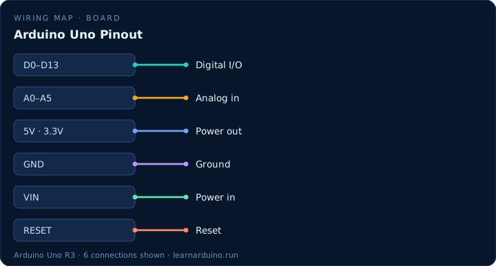
The Arduino Uno pinout, pin by pin
The silkscreen groups the pins, but the alternate functions are what trip people up. D0 and D1 are the hardware serial port the USB chip talks over. D2 and D3 can fire an interrupt. D10 to D13 double as SPI — SS, MOSI, MISO and SCK — and the same four lines are broken out again on the ICSP header, which is how shields reach them. A4 and A5 carry I2C as SDA and SCL, and AREF next to them lets you set a different reference voltage for the ADC.
Current is the other half of the pinout. The ATmega328P rates each pin at 40 mA absolute maximum and 20 mA recommended, with 200 mA across all of them at once. The 5 V pin is a different budget: it comes from the USB supply or the regulator, and roughly 400–500 mA is what you can draw before the polyfuse or the regulator gives up. VIN accepts 7–12 V and feeds the regulator, not the 5 V rail directly.
R3, R4 and clone boards: what changes
The R3 is the board this course targets: ATmega328P, 5 V logic, 16 MHz, 32 KB of flash. The R4 Minima and WiFi keep the same header layout but swap the chip for a 32-bit Renesas RA4M1 — plus an ESP32-S3 on the WiFi version — which brings a 14-bit ADC, a CAN controller and far more memory. Sketches written for the R3 mostly run unchanged; anything that pokes at registers does not.
Clones are a different matter. Most use the same ATmega328P and behave identically, but the USB-to-serial chip is usually a CH340 rather than the ATmega16U2. On macOS and Windows that means a one-off driver install before the board appears as a port. If it powers up, blinks, and never shows a serial port, the driver is the first thing to check — not the sketch.
The sketch
void setup() {
  pinMode(LED_BUILTIN, OUTPUT);  // pin 13, the "L" LED on the board
}

void loop() {
  digitalWrite(LED_BUILTIN, HIGH);  // 5 V on the pin
  delay(1000);                      // one second on
  digitalWrite(LED_BUILTIN, LOW);   // back to ground
  delay(1000);                      // one second off
}
What the code does
- LED_BUILTIN is a constant that always points at pin 13 on an Uno, so the same sketch runs on other boards too.
- pinMode(pin, OUTPUT) tells the chip to drive the pin instead of listening to it.
- digitalWrite(pin, HIGH) connects the pin to 5 V, which lights the LED; LOW connects it to ground.
- delay(1000) waits one second. Inside setup() it runs once, inside loop() it repeats forever.
Specifications
| Item | Value |
|---|---|
| Microcontroller | ATmega328P |
| Operating voltage | 5 V |
| Input voltage | 7–12 V |
| Digital I/O pins | 14 (6 PWM) |
| Analog inputs | 6 |
| Flash memory | 32 KB |
| SRAM / EEPROM | 2 KB / 1 KB |
| Clock speed | 16 MHz |
| Size | 68.6 × 53.4 mm |
Common mistakes
- Powering a motor or a servo from the 5 V pin. The pin can give about 400 mA in total before the board browns out — use a separate supply and share only ground.
- Using pins 0 and 1 for a sensor while the USB cable is plugged in. The serial monitor and your sensor fight over the same two pins.
- Expecting 3.3 V to run a whole module. That pin is limited to roughly 50 mA; it is meant for a reference voltage, not for power.
Sources
The figures in this lesson come from these documents. Every value in the tables above can be checked against them.
- Arduino Uno Rev3 — official board specifications
- pinMode() — Arduino language reference
- Analog inputs — how the Uno's ADC works
Frequently asked questions
How many PWM pins does the Arduino Uno have?
Six: 3, 5, 6, 9, 10 and 11. They are marked with a tilde (~) on the board and each one runs at about 490 Hz, except pins 5 and 6 which run near 980 Hz.
Can I use the analog pins as digital pins?
Yes. A0–A5 are also digital pins 14–19, so you can call pinMode(A0, OUTPUT) or digitalWrite(A0, HIGH). The reverse is not true: only A0–A5 can read a voltage.
How much current can one pin supply?
40 mA absolute maximum per pin, 20 mA recommended, and 200 mA in total across all pins. Anything that draws more — a motor, a relay, a strip of LEDs — needs a transistor or a driver board.
What is the difference between VIN and 5V?
VIN is the raw voltage from the barrel jack, 7–12 V. The 5 V pin is the regulated output of the on-board regulator, and it can also be used as an input if you power the board from a stable 5 V source.
Want to see this circuit before you own the parts? The Arduino simulator draws this exact pin table on a 3D Uno R3: click any jumper to see what it carries, press Run and read the serial monitor.
Open the Arduino simulatorPublished 12 November 2026 · last updated 19 November 2026 · written and tested by Nick Hu.